Homemade 2KW power inverter with circuit diagrams
Homemade 2KW power inverter with circuit diagrams
Homemade 2KW power inverter with circuit diagrams
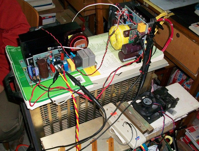
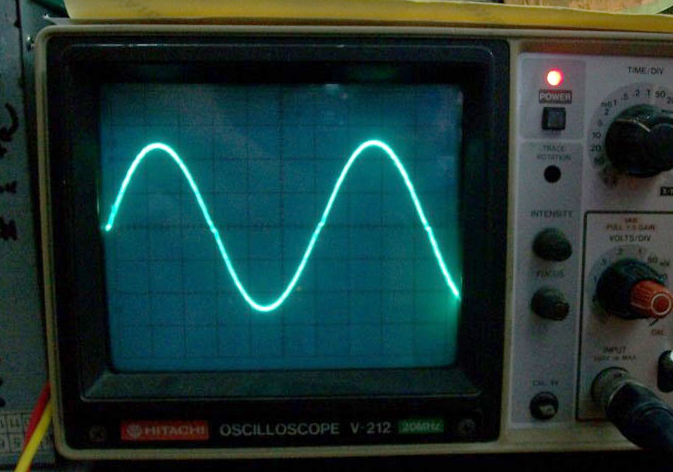
Not many days prior, Go Hz made a 24V 2000 W power inverter in house, sharing some design schematics and circuit outlines. Power inverter testing. The picture was taken in a nutshell. Output waveform. The SPWM precision of EG8010 wasn’t high enough waveform, so the sonic output wasn’t good enough as a pure sine wave. The dead zone time was somewhat long, where the zero-crossing point didn’t look good, so as to guarantee the safety of the tube, GoHz didn’t adjust it. This was a complete load test on the electricity inverter, two water heaters, approximately 2000 watt, the water has been brewed entirely.
The maximum connected load was 3000 volt for approx 10 minutes, as a result of the DC power source restriction, GoHz didn’t continue to test it. Adjust the inverter power limit potentiometer, limit the maximum energy at 2500 watt, the power inverter works for under two minutes until it turns off the output. Short circuit protection can also be set for approximately two minutes to turn off the output. Because of the EG8010 programming reason, the power sonic will continually work following a couple of moments if the force source isn’t cut off. This power inverter has a good beginning ability, it just takes about 1 minute for two parallel 1 million watt solar lamps.
This inverter was made to electricity about 2200 watt, the headline of the paper is 2000 watt is since the DC power source maximum output is 100A, therefore GoHz analyzed it in 2000 watt, for over 12 hours testing, it might work well at 2000 watt, there’ll not be any problem for the actual load in 2500 watt. This is the Main tube D level waveform when the electricity sonic was in 2000 w full load. Expanding the fireline tube D degree waveform when the inverter in 2000 w full load. This is the power sonic in the no-load power consumption test.
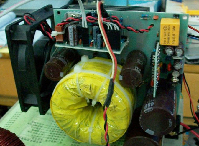
It may be seen from 2 multimeters, no-load electricity consumption is 24.6 0.27 = 6.642W, no-load consumption is fairly low, it may be used for photovoltaic, car batteries along with other new energy systems. Forward toroidal transformer. Stacked two 65 35 25mm ferrite rings, essential 3T with 16 1mm links, the auxiliary has been utilized an extremely fine multi-strand link tangled injury of 42T,
Utilizing 4 sets ixfh80n10, 80A, 100V, 12.5 milliohms resistors.
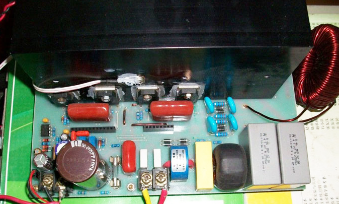
Rectifiers are 4 sets MUR1560, Two large electrolytic 450V470uF, 4 35V1000uF Japanese compound capacitors for 24V DC input. The backward electricity tube is 4 set FQA28N50, output inductor is sendest 52mm with 1.5mm vitreous enamel wire wrap 120T, inductance 1mH, capacitors are 2 sets 4.7uF safety capacitors. Two large frequency arms FQL40N50, and 2 low frequency FQA50N50 arms. Short circuit test.
- DC-DC power circuit board, conventional push-pull. (Download PDF file)
- The circuit is conventional SG3525 + LM393. (Download PDF file)
- The power inverter in a short circuit. (Download PDF file)
- SPWM driver board circuit, EG8010 + IR2110, to detect the voltage drop for short circuit protection. (Download PDF file)